Residential Cabling Specifications
Reproduced with permission from Fluke Corporation. All rights reserved.
Residential Cabling Specification
Fluke Networks prepared this document to aid in developing specifications covering residential cabling installations. It is offered as a general guide. Suitability for any intended use is the responsibility of the user. This document may be copied without Fluke Networks permission. This specification is not a substitution for the purchase of ANSI/TIA/EIA-570-B.
General
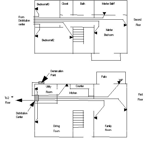
The residential cabling shall be installed to maximize its performance in support of home technology. For example, this technology may include systems such as computer networking, telephone, television, security and home automation (e.g., HVAC control, lighting). For computer networking and telephone cabling, category 5e or category 6 cabling shall be installed in home runs from the distribution center to the outlets (see figure 1). For cable TV or satellite TV, Series 6 (RG-6) quad shielded cable is generally installed. Within the home, each outlet generally consists of two category 5e or 6 cables and two Series 6 cables. Where cable extends to a device on the outside of a home, exterior-rated cable shall be used.
Various device locations must be identified such as those for voice, data, video (VDV) and whole-home audio applications including the distribution center. The device, outlet and distribution center locations can usually be determined from reviewing the home blueprints. The locations marked on the plans determine the wall and general locations for a device. The exact locations are determined in the field since the plumbing, electrical, and HVAC systems may fill stud bays. Each of these locations should be numbered and labeled in a consistent manner.
Cable rough-in
The rough-in for an outlet may consist of a square drawn cover (better known as a mud ring) or a backbox placed on a stud at the same height as the electrical outlets or the light switches for such items as volume controls and wall phones. While conduit is not usually needed for low-voltage cabling, some homes include conduit as an effective path for feeding cable through cement slab floors and to make future outlet changes.
The distribution center should be mounted within a climate-controlled location, thereby protecting the electronics from environmental damage. In addition, the distribution center shall contain or be located near a dedicated 120 V, 20 A power source to supply data and video electronics. The distribution center may be flush mounted within a stud bay or surface mounted on a basement (or other available) wall. In the case of surface mounting, a inch plywood backboard should be affixed to the wall first prior to mounting the distribution center to the backboard.
Locations for vertical and horizontal pathways must be established. In some forms of construction, the joists and studs are not wood, but are comprised of a sheet-metal frame. Where sheet metal framing is used, install grommets to protect the cable from the sharp metal edges. Penetrations through joists and studs may be no closer than 1 inches from the edge of the member in accordance to the National Electrical Code (NEC). Where this is impossible, a steel plate of at least 1/16 inch thick must be installed to protect against nails or screws penetrating the wiring.
Maintain as much distance between these low-voltage cables and the electrical cabling as possible. A minimum of 12 inches of separation should be maintained. Speaker wiring shall be run separate from all other wiring and maintain a minimum of 12 inches separation. If the paths of the two services are required to cross, do so at a 90- degree angle, if possible. Maintain a minimum of 12 inch spacing between the low-voltage cables and light fixtures.
Each cable shall be labeled for ease of identification during the cable pull. Carefully pull cables to avoid exceeding maximum pull tensions (e.g., category 5e and 6 cables are rated at 25 lbf) and avoid pinching of the cable around corners keep the cable with smooth bends. The cable bend radius for category 5e and 6 cables must not be less than 1 inch. The bend radius for Series 6 coaxial cable must not be less than 2 inches. These sweeps should be maintained both in cable runs and at termination points.
Once rough-in is complete, a verification test of the cabling shall be performed. This verification test will provide the installer with the knowledge that the cable was not nicked by nails or screws which damaged the cable and could cause a return visit later where sheetrock could need to be removed for running new cables. To aid in the trim-out phase, the cables could be terminated during rough-in and protected in plastic bags within the distribution center and backboxes for subsequent placement into faceplates after installation of drywall and painting.
Trim-out
At trim-out, all the cables are terminated to the cable and testing is completed. Proper cable termination practices are vital for the complete and accurate transfer of both analog and digital information signals. For low-voltage outlets and devices, ensure that all cables and terminations are properly labeled. In distribution centers, ensure that blocks, panels, or modules are installed in accordance with the designed layout and manufacturers recommendations. For all terminations of cables, follow the manufacturer instructions.
Insulation displacement connector (IDC) termination is generally used when terminating category 5e or category 6 cabling. Specific tools designed for making IDC terminations are required. Security and audio cables are usually connected with mechanical crimp or screw-type connectors. The size of the crimp connector that may be used for coaxial cable is dependent upon the diameter of the cable. Generally a Series 6 cable (RG-6) will be used.
Remove only as much of the sheath as is necessary to terminate category 5e and 6 cable pairs and ensure that the twist of the pairs is maintained up to the termination point on the connector. A maximum of inch of untwisting of pairs from the termination point for each cable pair shall not be exceeded.
The typical termination of coaxial cables will be on either Bayonet Neil-Concelman (BNC) or F connectors. There are many manufacturers of coaxial cable connectors available in the industry and may require slightly different termination methods. Always refer to manufacturers guidelines for detailed information.
Field Test Requirements
Low-voltage cables, such as those used for data systems, are typically designed to meet strict performance requirements. This type of cabling can be damaged during the construction phases of rough-in, drywall installation, and even siding of the exterior. Many of these faults are found in the pre-wire phase of construction resulting from causes such as nail and staple holes in the cable, severe kinks in the cable where the cable was pulled through a drilled hole in a stud or joist, or a cable tear where the cable sheath and conductors are damaged from the pull. For these reasons, its important that low-voltage cabling is thoroughly tested through a relatively simple process of verification and certification.
Verification testing confirms full and proper continuity and the absence of faults commonly created during the installation process. Certification testing confirms that the installed cablings performance meets or exceeds the appropriate category of cabling (category 5e or 6). In either case, cabling that passes field testing requirements will show that problems occurring later in the life of the home will be due to other reasons such as system abuse or damage from individuals other than the installer. From a cabling installers perspective, testing and documentation will provide the assurance that the cabling was installed correctly. For the owner and builder, it will provide confidence in the workmanship and quality of the installation.
All cabling shall be recorded and documented including the test results. Summary documentation shall be documented in the distribution center while detailed results from the certification test instrument shall be provided to the builder, or the homeowner.
Field test instruments for certification and verification testing
Test tools that can aid in certification and verification testing of copper cabling include the tone test set, the inductive probe, the craftspersons handset (buttset), a verification field test instrument, and a certification field test instrument (level IIe or greater). These tools work with all types of cable for applications including telephone, data, CATV, HVAC, audio and security systems. The tone test set works in combination with the inductive probe, or the buttset. The tone test set emits a tone on the cable, which can be picked up by the inductive probe, or by connecting the buttset to the other end of the pairs within the copper cable. The inductive probe is used to detect the audible tone to trace and identify cable without damaging the insulation and may pick up the tone on cables within wall cavities. The inductive probe may have interchangeable tips to provide greater flexibility for inspecting wiring in tight spots, cable under tension, or cables that may be in larger bundles. Used together, these test tools will:
Locate individual wires in a cable run along with any breaks or terminations that might be present.
Test for continuity.
Check for shorts and opens.
Identify tip and ring (+) and (-) polarity
Verification Testing
Verification testing involves visual inspection of the cabling and continuity testing of cabling. Visual inspection shall be done for each cable run after the cable has been pulled in, prior to termination and installation of insulation and gypsum board to include:
- Obvious damage to cable.
- Incorrect bend radii.
Verification testing of the cabling shall include:
- Wire map;
- Length;
- Continuity to the remote end;
- Shorts between any two or more conductors;
- Crossed pairs;
- Reversed pairs;
- Split pairs; and,
- Any other mis-wiring.
Verification testing shall be performed on all low-voltage category 5e or 6 cabling that is bridged or not connectorized with a T568A connector on both ends. Additionally, verification testing shall be performed on all other low-voltage cabling. Examples of cables that should be verified tested may include:
- The cable between the telephone service provider demarcation point and the distribution center.
- Cable used for powering video cameras or IR targets and IR emitters.
- Cable for telephones that terminate on bridging modules.
- Audio cable for speakers and volume controls.
- Cable for control systems.
- Series 6 cable for RF Broadband, DSS, and CCTV.
Testing category 5e or 6 cabling that is bridged with a bridging module
Verification testing shall be done on category 5e or 6 cabling that terminates on a bridging module. The following procedure shall be used for verification testing of the cabling.
- Plug the remote unit into a modular jack that is known to be connected to the bridge module in the centralized distribution center.
- Plug the main unit into another jack that is also connected to the bridging module.
- Run the test from the main unit and record the results.
- Leave the remote unit where it is and move the main unit to another jack that is connected to the bridging module and run the same test. Continue to move the main unit to each jack connected to the bridging module while recording the results.
- All cables shall pass the wire map test. If any cable fails the test or if all cables fail the test, verify that all terminations at the jack are correct and follow the T568A pattern. Next, verify that all terminations at the bridging module in the central distribution center are correct. If all terminations look correct, disconnect one cable at a time from the bridging module and retesting the cabling until the trouble is found and corrected. The tester can determine pair polarity (wire map), excessive length, shorts, opens, and other problems in the cable runs.
Verification testing of cabling not terminated (e.g., audio cabling)
For un-terminated audio cable, use a verification test instrument or multimeter to verify any opens or shorts between wires in the speaker cables. First verify that there are no shorts between the individual conductors in each cable using a multimeter. Then, to check for continuity of each conductor, short the remote end of cable conductors to form a complete circuit loop. Check for continuity between the conductors on the cable.
Verification testing of Series 6 coaxial cabling
For Series 6 coaxial cabling, verification testing with a verification field test instrument will determine shorts, continuity, termination location and length of cable.
Certification Testing
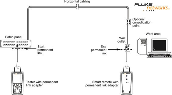
Certification testing shall be done on all low-voltage category 5e and 6 cabling where each end of the cable is terminated on connecting hardware and not bridged. Certification testing shall be done using a permanent link measurement (see figure 1). The permanent link refers to the permanent part of the cabling installed without patch cords installed on each end of the cable. See annex A for performance parameters for category 5e cabling.
Annex A Certification performance test parameters
The test parameters for category 5e cabling are specified in the ANSI/TIA/EIA 568‑B.1 standard. The test of each category 5e permanent link shall contain all of the following parameters as detailed below. In order to pass the link test all measurements (at each frequency in the range from 1 MHz through 100 MHz) must meet or exceed the limit value determined in the standard.
Wire Map
Wire Map shall report Pass if the wiring of each wire-pair from end to end is determined to be correct. The Wire Map results shall include the continuity of the shield connection if present.
Length
The field tester shall be capable of measuring length of all pairs of a permanent link or channel based on the propagation delay measurement and the average value for NVP. The physical length of the link shall be calculated using the pair with the shortest electrical delay. This length figure shall be reported and shall be used for making the Pass/Fail decision. The Pass/Fail criteria are based on the maximum length allowed for the permanent link configuration (90 meters 295 ft) or the channel (100 meters 328 ft) plus 10% to allow for the variation and uncertainty of NVP.
Insertion Loss (Attenuation)
Insertion Loss is a measure of signal loss in the permanent link or channel. The term Attenuation has been used to designate insertion loss. Insertion Loss shall be tested from 1 MHz through 100 MHz in maximum step size of 1 MHz. It is preferred to measure attenuation at the same frequency intervals as NEXT Loss in order to provide a more accurate calculation of the Attenuation-to-Crosstalk Ratio (ACR) parameter. Minimum test results documentation (summary results): Identify the worst wire pair (1 of 4 possible). The test results for the worst wire pair must show the highest attenuation value measured (worst case), the frequency at which this worst case value occurs, and the test limit value at this frequency.
NEXT Loss, pair-to-pair
Pair-to-pair near-end crosstalk loss (abbreviated as NEXT Loss) shall be tested for each wire pair combination from each end of the link (a total of 12 pair combinations). This parameter is to be measured from 1 through100 MHz. NEXT Loss measures the crosstalk disturbance on a wire pair at the end from which the disturbance signal is transmitted (near-end) on the disturbing pair. The maximum step size for NEXT Loss measurements shall not exceed the maximum step size defined in the standards as shown in Table 1, column 2. A smaller step size more accurately identifies worst case margin conditions (see summary results, below).
Frequency Range (MHz) | Maximum Step size (MHz) |
|---|---|
1 – 31.25 | 0.15 |
31.26 – 100 | 0.25 |
Minimum test results documentation (summary results): Identify the wire pair combination that exhibits the worst case NEXT margin and the wire pair combination that exhibits the worst value of NEXT (worst case). NEXT is to be measured from each end of the link-under-test. These wire pair combinations must be identified for the tests performed from each end. Each reported case shall include the frequency at which it occurs as well as the test limit value at this frequency.
PSNEXT Loss
Power Sum NEXT Loss shall be evaluated and reported for each wire pair from both ends of the link-under-test (a total of 8 results). PSNEXT Loss captures the combined near-end crosstalk effect (statistical) on a wire pair when all other pairs actively transmit signals. Like NEXT this test parameter must be evaluated from 1 through 100 MHz and the step size may not exceed the maximum step size defined in the standards as shown in Table 1, column 2.
Minimum test results documentation (summary results): Identify the wire pair that exhibits the worst case margin and the wire pair that exhibits the worst value for PSNEXT. These wire pairs must be identified for the tests performed from each end. Each reported case shall include the frequency at which it occurs as well as the test limit value at this frequency.
ELFEXT Loss, pair-to-pair
Pair-to-pair FEXT Loss shall be measured for each wire-pair combination from both ends of the link-under-test. FEXT Loss measures the unwanted signal coupling (crosstalk disturbance) on a wire pair at the opposite end (far-end) from which the transmitter emits the disturbing signal on the disturbing pair. FEXT is measured to compute ELFEXT Loss that must be evaluated and reported in the test results. ELFEXT measures the relative strength of the far-end crosstalk disturbance relative to the attenuated signal that arrives at the end of the link. This test yields 24 wire-pair combinations. ELFEXT is to be measured from 1 through 100 MHz and the maximum step size for FEXT Loss measurements shall not exceed the maximum step size defined in the standards as shown in Table 1, column 2. Minimum test results documentation (summary results): Identify the wire pair combination that exhibits the worst case margin and the wire pair combination that exhibits the worst value for ELFEXT. These wire pairs must be identified for the tests performed from each end. Each reported case shall include the frequency at which it occurs as well as the test limit value at this frequency.
PSELFEXT Loss
Power Sum ELFEXT is a calculated parameter that combines the effect of the FEXT disturbance from three wire pairs on the fourth one. This test yields 8 wire-pair combinations. Each wire-pair is evaluated from 1 through 100 MHz in frequency increments that do not exceed the maximum step size defined in the standards as shown in Table 1, column 2. Minimum test results documentation (summary results): Identify the wire pair that exhibits the worst case margin and the wire pair that exhibits the worst value for PSELFEXT. These wire pairs must be identified for the tests performed from each end. Each reported case shall include the frequency at which it occurs as well as the test limit value at this frequency.
Return Loss
Return Loss (RL) measures the total energy reflected on each wire pair. Return Loss is to be measured from both ends of the link-under-test for each wire pair. This parameter is also to be measured form 1 through 100 MHz in frequency increments that do not exceed the maximum step size defined in the standards as shown in Table 1, column 2.Minimum test results documentation (summary results): Identify the wire pair that exhibits the worst case margin and the wire pair that exhibits the worst value for Return Loss. These wire pairs must be identified for the tests performed from each end. Each reported case shall include the frequency at which it occurs as well as the test limit value at this frequency.
ACR (Attenuation to crosstalk ratio)
This parameter is not required by the ANSI standards but may be required in order to obtain the premise wiring vendor’s warranty] ACR provides an indication of bandwidth for the two wire-pair network applications. ACR is a computed parameter that is analogous to ELFEXT and expresses the signal to noise ratio for a two wire-pair system. This calculation yields 12 combinations – six from each end of the link. Minimum test results documentation (summary results): Identify the wire pair combination that exhibits the worst case margin and the wire pair combination that exhibits the worst value for ACR. These wire pair combinations must be identified for the tests performed from each end. Each reported case shall include the frequency at which it occurs as well as the test limit value at this frequency.
PSACR
This parameter is not required by the ANSI standards but may be required in order to obtain the premise wiring vendor’s warranty] The Power Sum version of ACR is based on PSNEXT and takes into account the combined NEXT disturbance of all adjacent wire pairs on each individual pair. This calculation yields 8 combinations – one for each wire pair from both ends of the link.Minimum test results documentation (summary results): Identify the wire pair that exhibits the worst case margin and the wire pair that exhibits the worst value for PSACR. These wire pairs must be identified for the tests performed from each end. Each reported case shall include the frequency at which it occurs as well as the test limit value at this frequency.
Propagation Delay
Propagation delay is the time required for the signal to travel from one of the link to the other. This measurement is to be performed for each of the four wire pairs. Minimum test results documentation (summary results): Identify the wire pair with the worst case propagation delay. The report shall include the propagation delay value measured as well as the test limit value.
Delay Skew
This parameter shows the difference in propagation delay between the four wire pairs. The pair with the shortest propagation delay is the reference pair with a delay skew value of zero. Minimum test results documentation (summary results): Identify the wire pair with the worst case propagation delay (the longest propagation delay). The report shall include the delay skew value measured as well as the test limit value.